BactoLink
Connectivity module for BactoSense and BactoSense Multi. This edition describes the BactoHub workflow and is valid from BactoSense software 2.2.
General user information
Intended use
BactoLink establishes a remote connection between the instrument and your PC. Initiate the connection through the BactoHub portal using HTTPS and a web browser. The portal is the access point for BactoLink and the associated instruments. A connection remains active for 30 minutes and must then be re-established.
Pictograms
Information notices provide additional details about the current topic. Numbered lists describe practical procedures. Screenshots are examples and may differ from the current device.
Overview and prerequisites
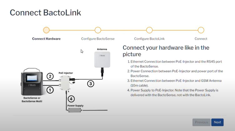
BactoLink consists of an antenna, an Ethernet cable and a Power-over-Ethernet (PoE) injector. The injector connects to the BactoSense or BactoSense Multi power supply.
Before installation:
- Check that the instrument runs software 2.2 or later.
- Activate DHCP and HTTPS in the instrument settings.
- Activate VNC if GUI relay is required.
- Make sure you have an account at hub.bnovate.com. Request an account from support@bnovate.com if needed.
Power-over-Ethernet injector
The PoE injector powers the antenna through Ethernet. Its Ethernet and power connections to the instrument are permanently integrated. It has a port for the power cable supplied with BactoSense, and an Ethernet connection to the antenna.
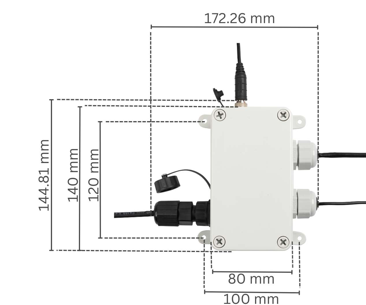
The injector height from its feet to its top is 65.5 mm.
| Mechanical specification | Value |
|---|---|
| Material | Polycarbonate (PC) |
| Connectors | RJ45, power connector |
| Protection | IP67 |
| Dimensions, L × H × W | 165 × 165 × 54 mm |
| Operating temperature | 5–30 °C |
Antenna
The antenna connects to the PoE injector through Ethernet and houses the SIM card for mobile connections (4G/LTE, 3G, 2G). See Mounting BactoLink for the mounting bracket.
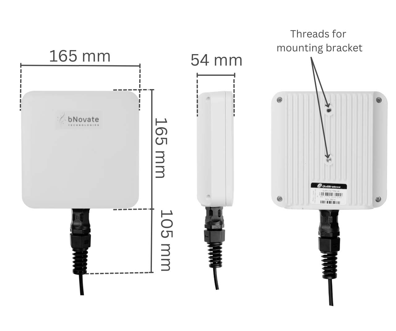
| Mechanical specification | Value |
|---|---|
| Materials | ABS, PC, FR4 |
| Connector | RJ45 |
| Protection | IP67 |
| Dimensions, L × H × W | 165 × 165 × 54 mm |
| Weight | 0.8 kg |
| Operating temperature | −40–80 °C |
Installation
Instrument connections
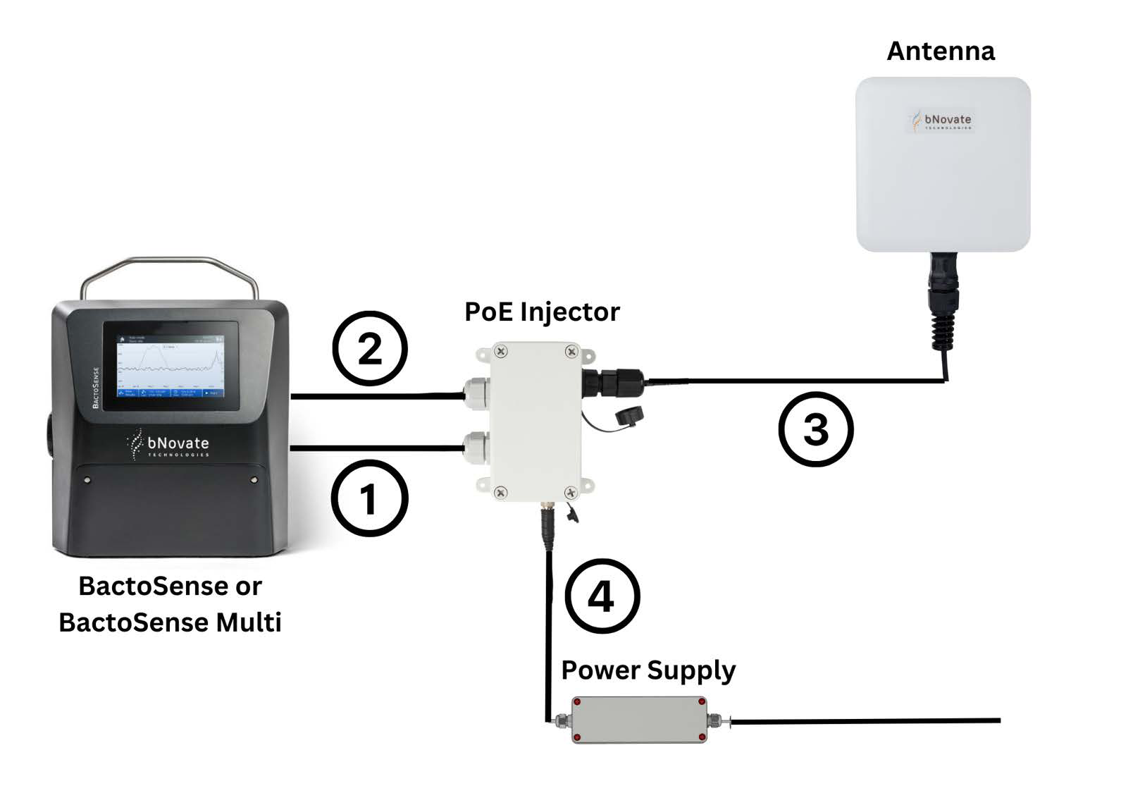
| Connection | Description |
|---|---|
| 1 | Ethernet between the PoE injector and the instrument's RJ45 port |
| 2 | Power between the PoE injector and the instrument's power port |
| 3 | Ethernet between the PoE injector and the antenna |
| 4 | Power supply to the PoE injector. The power supply is delivered with BactoSense. |
Connecting the antenna and PoE injector
-
Open the bag containing the Ethernet cable.
-
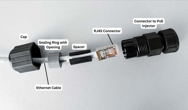
Open the PoE injector package and its separate connector bag. Take out the cap, sealing ring with opening, spacer and connector to the PoE injector. Line them up on the Ethernet cable as illustrated.
-
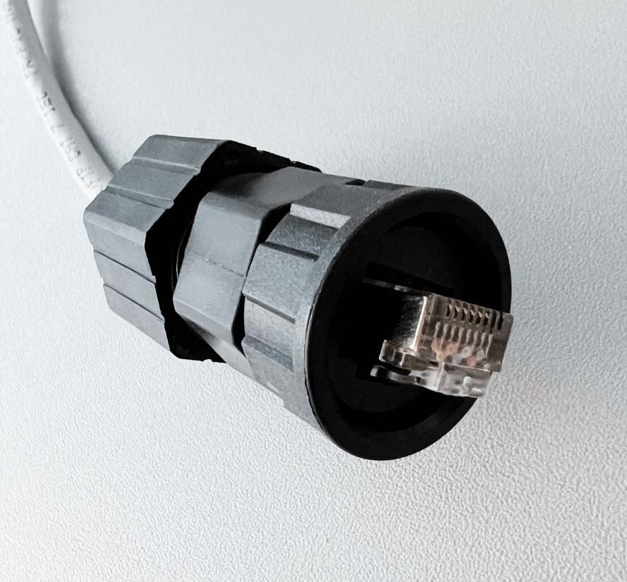
Guide the RJ45 connector into the PoE connector. Both allow only one orientation. Push the RJ45 connector as far forward as possible. Push the spacer and sealing ring into the PoE connector. Screw the cap on while gently pushing the parts together, until hand-tight. The resulting fitting is a bayonet fitting to the PoE injector.
-
Align the other end of the Ethernet cable in front of you.
-
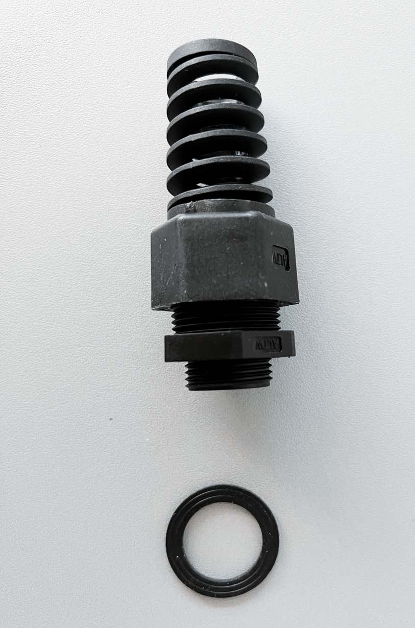
Take the antenna connector and O-ring from the antenna package.
-
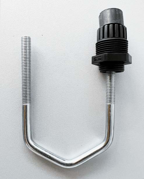
Unscrew the antenna connector and push out the sealing ring. If necessary, use the curved mounting rod to push it out.
-
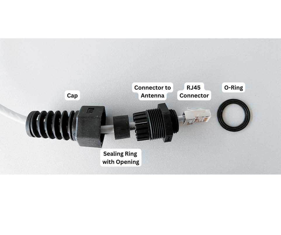
Align the antenna connector parts on the Ethernet cable as illustrated.
Assemble the antenna connector in orderConnect RJ45 to the antenna first, secure the connector to the antenna, and mount the cap last. This prevents the cable from being locked beneath the seal.
-
Push the RJ45 connector lightly into the antenna connector. Ensure its small tab is within the antenna.
-
Push the sealing ring into the antenna connector.
-
Put the O-ring on the antenna connector and connect RJ45.
-
Screw the connector into the antenna.
-
Screw the cap onto the connector.
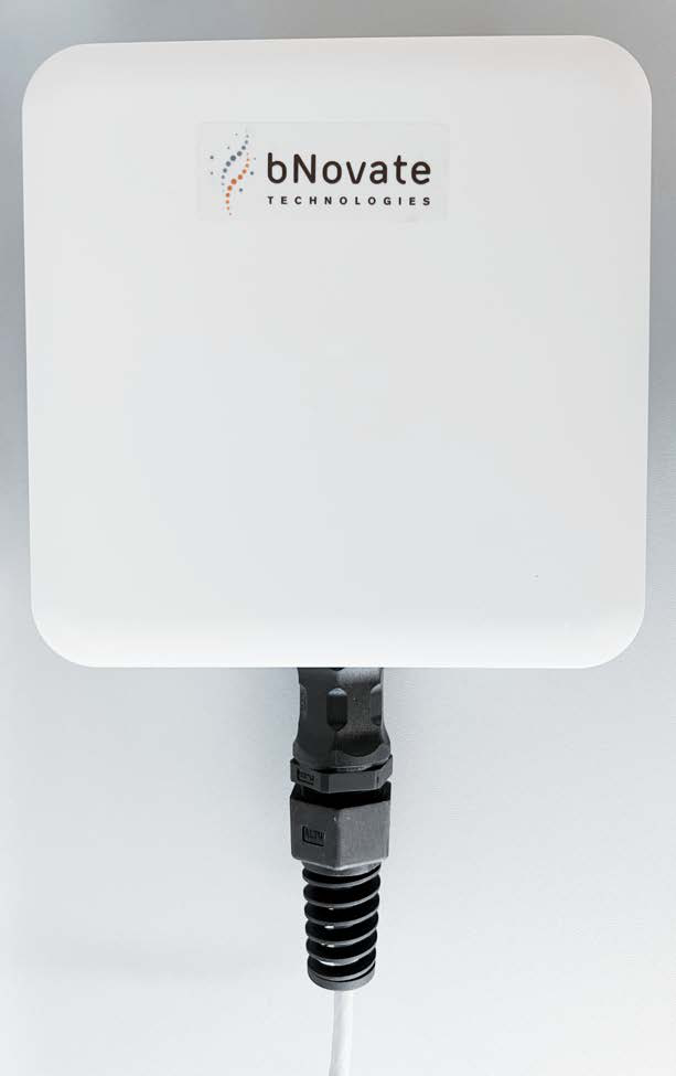
Mounting BactoLink
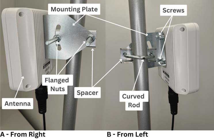
The mounting set attaches the antenna to cylindrical or square objects, pipes or rods.
-
Open the antenna package and locate the mounting bracket and assembly components.
-
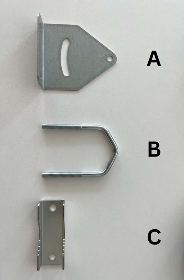
Identify the mounting plate (A), curved rod (B) and spacer (C). The plate attaches to BactoLink, the curved rod holds it in place, and the spacer maintains the distance between rod and plate.
-
Locate the two screws and washers in the antenna package.
-
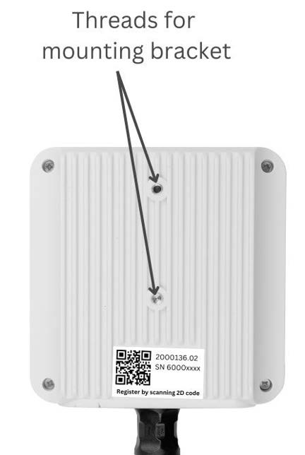
Position the mounting plate on BactoLink. Insert the screws through the plate into BactoLink, with washers between the screw heads and plate. Tighten with a 5 mm Allen key until securely attached.
-
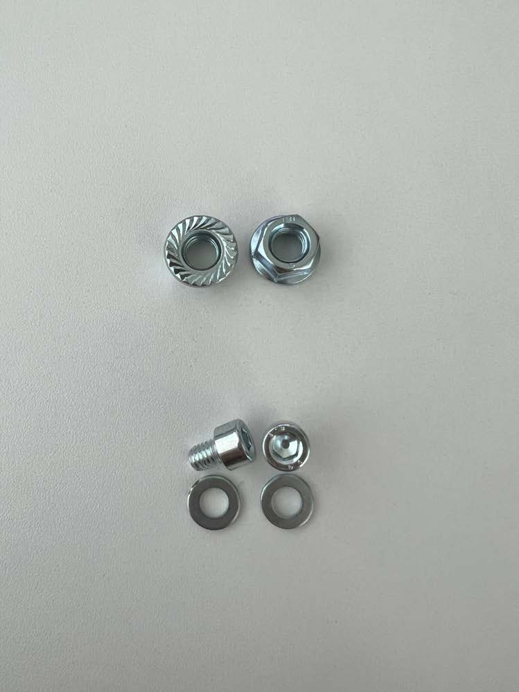
Locate the two flanged nuts.
-
Position the curved rod and spacer on the plate in the desired orientation.
-
Insert the two flanged nuts onto the threaded ends of the curved rod. Hand-tighten, or use a 13 mm wrench, until the nuts do not move and BactoLink is securely attached.
First installation
-
Check that the instrument runs software 2.2 or later. For an upgrade, contact support@bnovate.com.
-
Scan the 2D barcode on the back of the antenna. Enter the username and password previously chosen for BactoHub. If you need an account, contact support.
-
Power off the instrument. Connect the devices as described in Instrument connections and Connecting the antenna and PoE injector.
-
Power on the device.
-
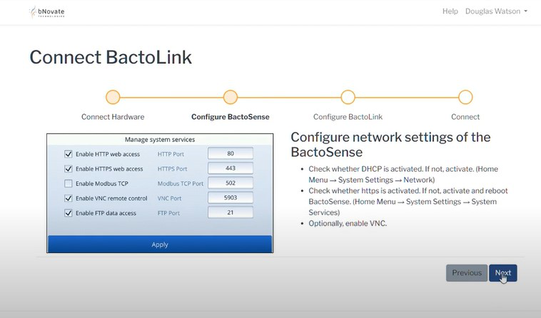
Open Home → System Settings → Network. Activate DHCP if necessary.
Wait before restartingDo not power cycle the instrument immediately.
-
Open Home → System Settings → System Services. Activate HTTPS for WebUI access and assign port 443. If changed, reboot BactoSense. HTTPS is required for BactoLink to function. Power cycle the instrument, or first perform the optional next step.
-
If GUI relay is needed, activate VNC, assigned to port 5900, under System Services. Then power cycle the instrument.
Remote screen visibilityWith GUI relay, your screen actions are visible to people at the instrument and remotely connected users. Confidential information might be shared.
-
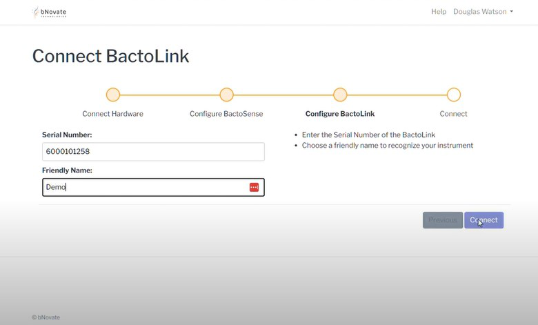
Configure BactoLink using its serial number and a user-friendly name. Click Connect.
-
Wait until the instrument is connected, then click Finish.
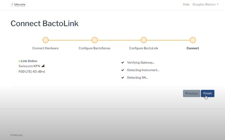
-
The instrument appears in the BactoHub instrument list. Choose WebUI or GUI relay. The connection opens in a separate tab and remains valid for 30 minutes. Reconnect after that period.
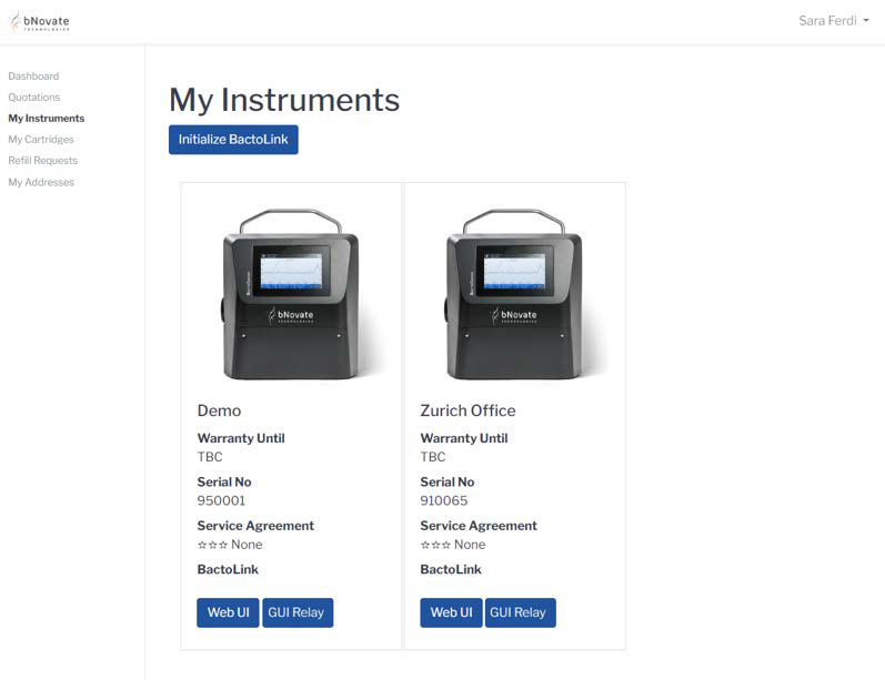
Reconfiguration of BactoHub
- Click Initialize BactoLink below My Instruments. Enter the instrument serial number and a user-friendly name, then press Continue.
- Repeat steps 2–9 of First installation. You can then access the instrument through WebUI and GUI relay.
Remote connections
Web User Interface (WebUI)
The WebUI provides access to instrument data through the RJ45 port. Click WebUI in BactoHub to establish a connection through BactoLink. If you reboot BactoSense through the WebUI, reload the web page as well.
Password
When prompted, enter the BactoSense device username (Basic, Advanced, Admin or Service) and its chosen password.

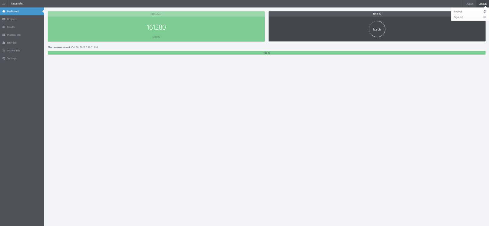
Dashboard
The dashboard provides the latest measurement results, instrument status and warnings for expired cartridges.
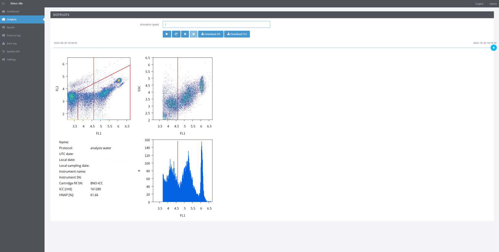
Dotplots
Dotplots show an animation of recent measurements. Loading can take time, depending on the connection. Start with animation speed 1; use higher speeds once the images are fully loaded. Download options are available in GIF and FCS formats.
Results
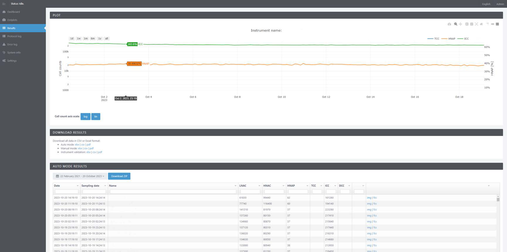
Results show measurements over time and provide download options. Below the plot are download areas for auto mode, manual mode and instrument validation. Auto and manual results are listed at the bottom. View them as a table, download cumulative ZIP files, or download IMG and FCS files for each measurement. BactoSense Multi shows only manual mode and has no time series plot.
Protocol Log
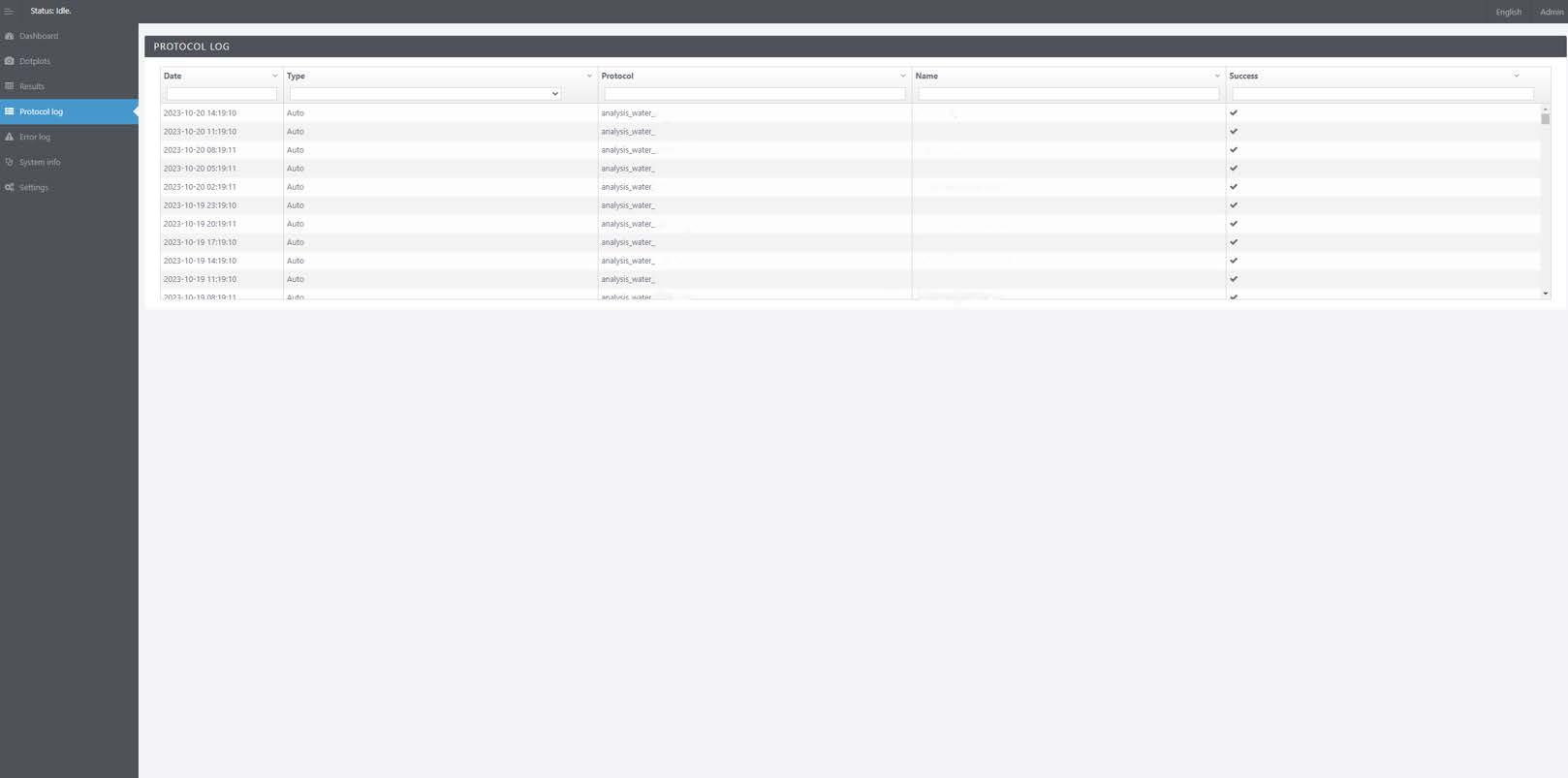
The Protocol Log shows executed protocols and error messages. Download the data as CSV.
Error Log
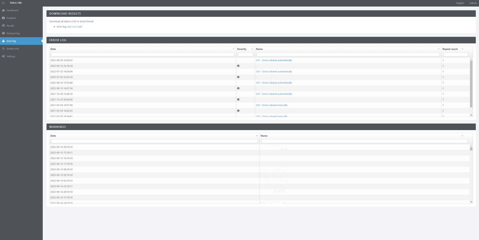
The Error Log lists errors and warnings, downloadable as XLSX, CSV or PDF.
System Info
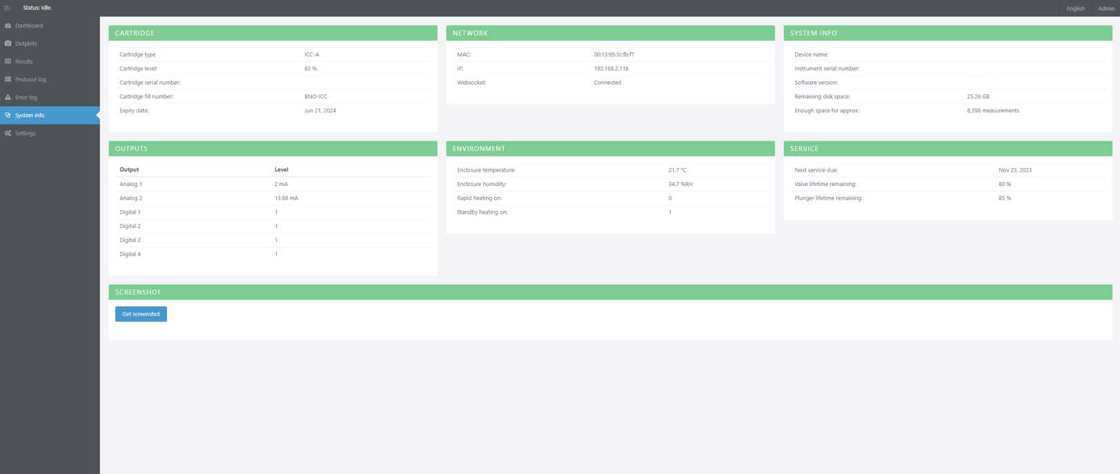
System Info provides general system information and allows screenshots to be taken.
Settings
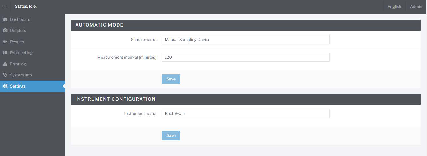
Settings allows changes to sample names, measurement intervals and instrument name. It is unavailable for BactoSense Multi.
Graphical User Interface Relay (GUI relay)
GUI relay provides remote desktop access as if you were physically present at the instrument.
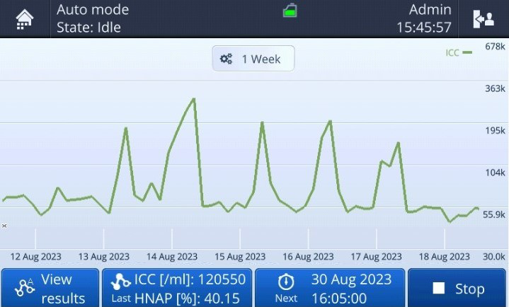
Your screen actions are visible to people at the instrument and remotely connected users. Confidential information might be shared.
Troubleshooting
If the instrument was turned off during installation, BactoLink should work immediately. If issues persist:
- Make sure BactoLink is fully powered on before powering on BactoSense. Allow at least 3 minutes for the instrument to establish a network connection.
- Check mobile network connectivity at the location using your mobile phone.
- If no connection is possible, disconnect and reconnect the antenna from the PoE injector to power cycle the antenna.
- Inspect all connections on the injector and connected instruments.
- If problems persist, power cycle BactoSense.
Publisher and contact
© bNovate Technologies SA. Subject to technical changes without notice, October 2023. Written by bNovate Technologies SA. Copying, modifying or distributing the document to third parties requires the publisher's express consent.
bNovate Technologies SA, Ch. Dent d’Oche 1A, CH-1024 Ecublens, Switzerland. Telephone: +41 21 552 14 21. info@bnovate.com · www.bnovate.com.